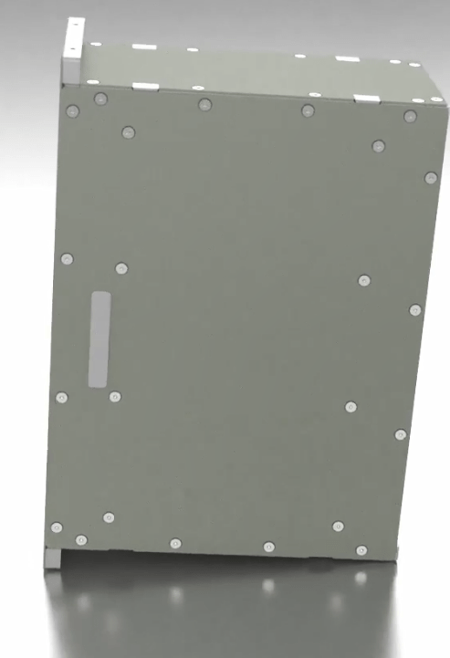
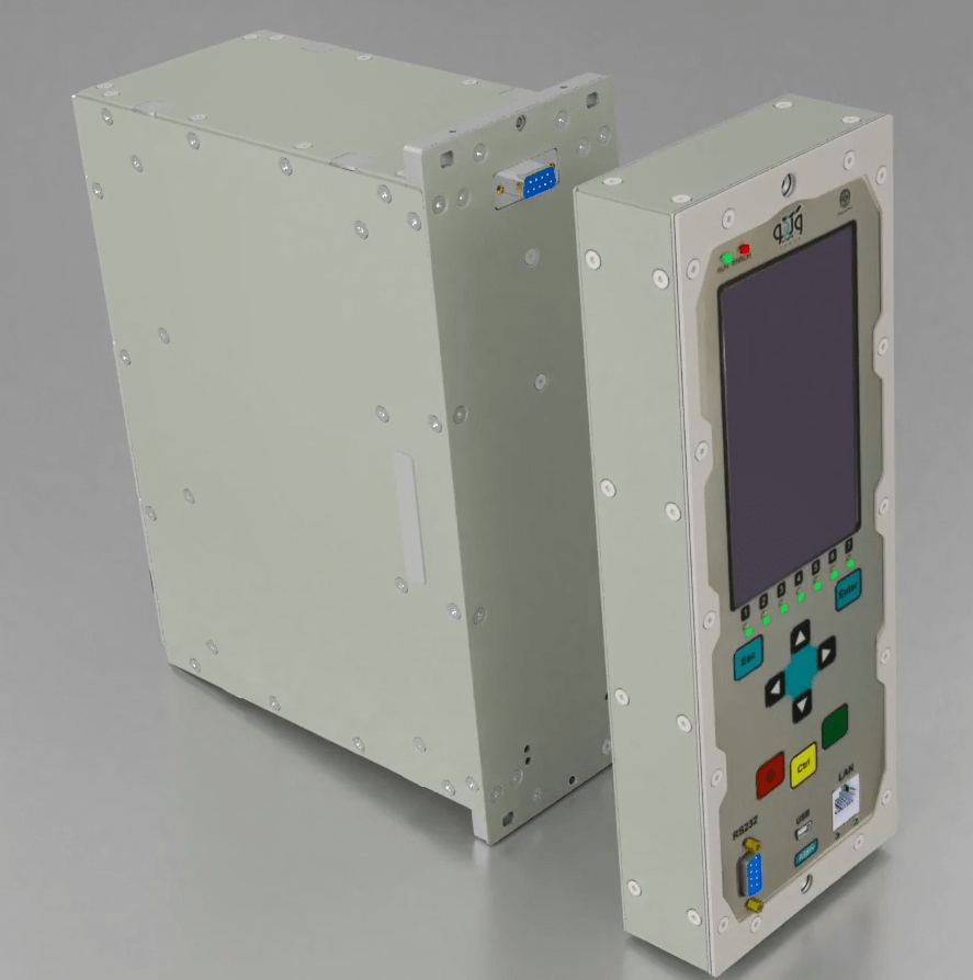
The metallic main case of the “AMR” relay is designed and made of Aluminium3105 by experts at Vebko company and different modules of relay are placed in the integrated racks. To begin the assembly, the front panel of “Main Case” is opened.
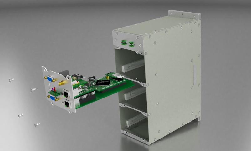
To prepare “MidPlate”, micro module is placed on it and the front panel of “Mid Case” which has been opened before is placed on “MidPlate” module and its screws are tightened. After doing this, the front panel along with “MidPlate” is placed on “Main Case” module and its screws are tightened.
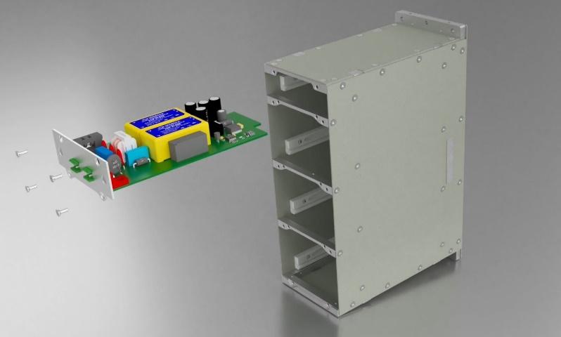
Back panel of “PS” or power supply card is placed on “PS” card and its screws are tightened. Then, the “PS” card is placed inside the “main case” and the related screws are tightened.
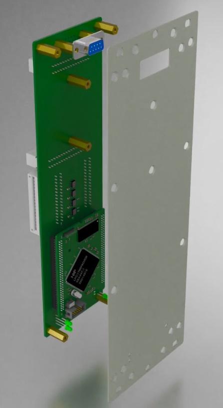
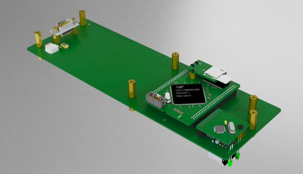
“MSD” module along with related spacer is placed on the micro module and its bolts are tightened from beneath. The micro module is placed on “Main Card” as the main “CPU”. Then, “LAN-WiFi” module is placed in the related place on “Main Card” and is tightened from beneath using 2 screws and spring washer. Also, the “GPS-RS485” module is placed on the two spacers at the top of “LAN-WiFi” module and is tightened using 2 bolts and spring washer and then, using a communication flat, “GPS” module is connected to “Main Card”. Next, “Back Panel” of the “Main Card” is placed on the card and, by using the related bolts, is tightened to the “GPS” antenna of the “Back Panel” along with 4 spacers. Finally, the “Main Card” is placed inside the case and its screws are tightened.
To prepare this card, “AD gain” module is placed in its related place on “PT-BO” card and is tightened from beneath using screws and spring washer. Then, four “PT” modules are placed in their related place on “PT-BO” card and its screws and spring washer are tightened from beneath. At this stage, BO module (Binary Output) is placed on 41 millimeter spacers and its bolts and spring washer are tightened. Then, the communication flat between “BO” and “PT-BO” is connected. After that, the back panel of “PT-BO” card is connected to “PT-BO” card using 4 screws and then this card is placed in its designated place in the case and then its screws are tightened.
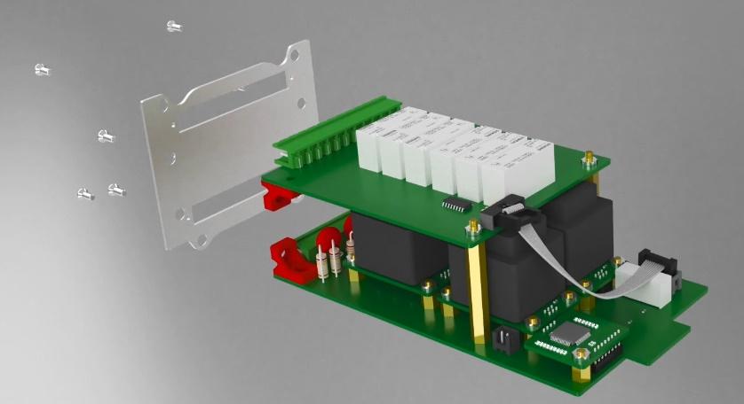
In preparation of this card, barrier connector is connected to the “Back Panel” of “CT-BI” card and this “Back Panel” is connected to “CT-BI” card. At this stage, “AD Gain” module is placed on “CT-BI” card and tightened using screws and spring washer. Now, four “CT” modules are placed on “CT-BI” card and its screws and spring washer are tightened. Then, a 2.5 strand wire is passed through “CT”s and is soldered after swinging to the barrier connector. Then, the connections are covered using varnish (or shearing). At this stage, “BI” module (Binary Input) is placed on 43millimeter spacers and its 3 screws and spring washer and the screws of its back panel are tightened. Next, its communication flat is connected to “CT-BI” card. Finally, the “CT-BI” card is placed in its integrated place in the case and its 4 screws are tightened.

The first step in preparing “Front Panel” is opening the back panel of “LCD-CASE”. Then, “LAN” module is placed on “Front Panel” module and its screw and spring washer are tightened. Next, “MSD” module along with the related spacer is placed on micro module and its bolts are tightened from beneath. In the end, the Micro module is placed on “Front Panel”.
After closing the back panel of “LCD-CASE” in the back of “Front Panel”, “RS232” module is placed on “Front Panel” and its 3 screws and spring washer are tightened. Finally, “LCD” is placed on “LCD” module and its related flat is connected and then “LCD” module is placed on “Front Panel” module and its 4 screws and spring washer are tightened. After preparing the “Front Panel” board, it is placed in the main case of “LCD-CASE” and its screws are tightened to the back panel.
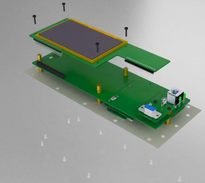
At the final stage, the front panel of “LCD-CASE” is opened and a label is stuck on it. Then, the flat label is connected to the related pin header on “LCD” module and the plate is placed in its designated place and its screws are tightened. Note that there are two spacers placed on “Front Panel” and the “Front Panel” is connected to the relay main case using two 4*50 screws.
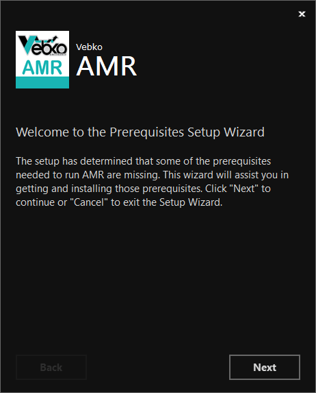
To prepare the latest version of AMR software, go to www.vebko.org website and in the software tab, download section of the latest version of relay software (AMR), click on the download option. After preparing the latest version of the software, you should install it on your system. Note that you don’t need to uninstall the old version on the system to install the new version, and this will be done automatically by the new version. You can also manually uninstall the existing version through control panel\Programs\Programs and Features on your system and then install the new version. Run the AMR.exe file to install the software. In the opened page to continue the installation process, click on Next option.
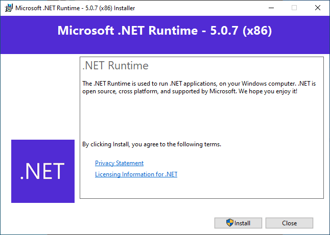
In the next section, two Microsoft .NET Runtime 5 and Microsoft Windows Desktop Runtime 5 programs that are prerequisites for the software is displayed, these programs must be installed on the system before the original software is installed, if these programs are available on the system, you can prevent them from reinstalling by unticking them, otherwise they will be installed later.

Click on the Next option. In the opened window, by clicking on the Install microsoft .NET Runtime -5.0.7 (x86) app is installed on the system and click on close option after installation is finished.
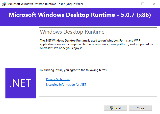
Also, in the next opened window, by clicking on install the Microsoft Windows Desktop Runtime - 5.0.7 (x86) app is installed on the system and click on close option after installation is finished.
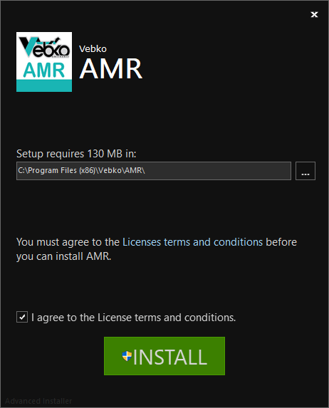
After completing the installation of the prerequisite programs, the installation of the main software begins. In the Setup requires section, you can change the installation location of the software, then tick I agree to the license terms and conditions option and click on Install. Note that installing the AMR software takes a few seconds.
After the installation process is finished, the AMR has been successfully installed message is displayed, by clicking on the Finish option, the installation window is closed and a Shortcut file named AMR is created on the desktop.
To open the AMR software, you can double click on the Created Shortcut file in the desktop, or directly click on the software icon in the Start menu by searching for the name AMR, and then login to the software environment.
The home page of the software consists of three parts:
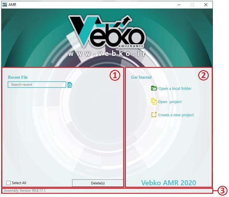
Recent Projects
Get Started
Assembly Version
In the "Assembly Version" section, information about the software version is written. In the "Get Started" section, you can log in to the software homepage by creating a new project or by opening an existing project on the system. By selecting the open default directory option, the default path for projects which are saved on the system opens. To open an existing project on the system, click on Open project, then in the opened window, select the project from its path and click on the Open option. To create a new project, click on create a new project option, then in the opened window select the path to save the project and click on Save option. It should be noted that projects are saved by default with the name AMR Project along with the date and time of their creation. After creating the project, the main software environment opens.
Also, in the main software environment, you can use the File menu and select the New option to create a new project, the Open option to open a project, and Recent to access recently opened projects.
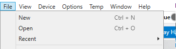
Ctrl+N combination keys for creating new project and Ctrl+O are also intended to open a project. It should be noted that the software automatically saves a backup of the running project every three seconds, if for any reason the software crashes, by re-running the software and opening the same project, the Crash Files window opens where the saved backup files are listed in order of the time, by selecting each of these files, the project with the last minute changes opens. After the project opens, these Backup files are deleted.

To connect the relay with the software, the network cable must first be connected to the LAN port behind the relay and the other side to the laptop. In order to connect, an IP range must be defined for the system interface according to the laptop operating system. These settings are checked for Windows 10: in the Start menu, Control Panel is searched and opened, then in the opened window click on the Network and Internet icon.

Then click on network and Sharing Center option.

Then on the left side of the window, click on change adapter settings option.

In the opened window, double click on the Ethernet icon.
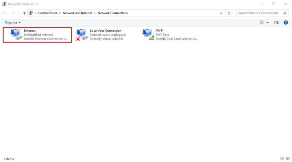
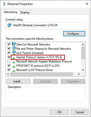
In this section, there might be a large number of Ethernet or Local Area Connection interfaces, to ensure that the correct interface is selected, the network cable can be removed from the system once, in which case a red cross on the icon is placed and after reconnecting the cable, the red cross is removed from the desired icon. In the opened window, double click on Internet Protocol Version 4 (TCP/IPv4) option.
In the opened window, select radio button use the following IP address and enter the range of 192.168.1.20 in the IP address section.
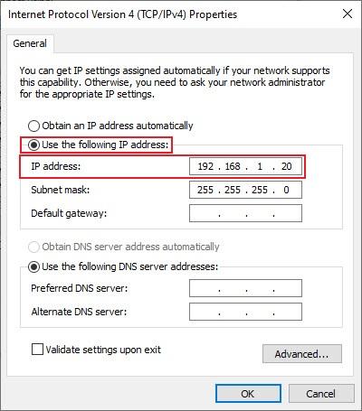
By adjusting this IP range, the 255.255.255.0 range is automatically placed in the Subnet mask section. Finally, click on OK and also in the windows that have been opened before it, click on ok option.
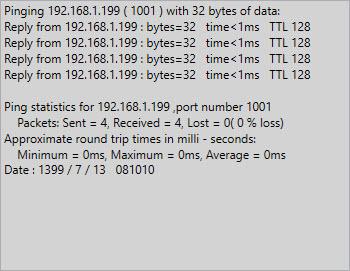
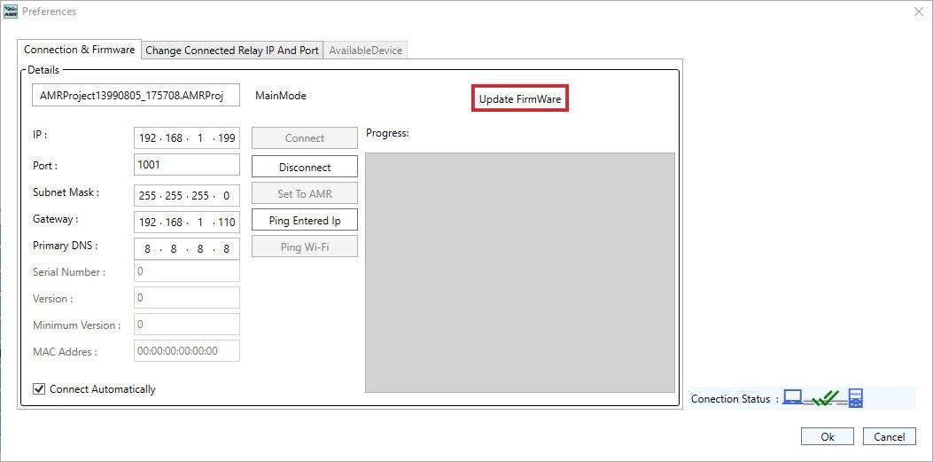
After connecting the network cable and doing the required settings, the Preferences window should be opened by double-clicking on the Connection Status icon, then the relay IP is entered in the IP section. This IP is 192.168.1.199 by default, which can be changed.

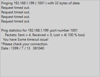
To check the software and relay connection in the Local network, click on the Ping entered IP option. If you are connecting the replay from 192.168.1.199: bytes=32 time<1ms TTL 128 message is repeated and in case of no connection, request timed out message is repeated.
After checking the connection, by clicking on connect option, the software connects to the relay and two green ticks are placed on the Connection Status icon. If the Connect Automatically option is ticked, the Connect command is automatically sent to the relay every 3 seconds if the connection is disconnected. To disconnect the software and relay, you can click on disconnect option, in which case the tick of the Connect Automatically option is also removed.
To change the relay IP, while the software and relay connection is established, in the Preference window, the existing IP is deleted and the desired IP is entered, then by clicking on set to AMR option, this IP is set on the device. It should be noted that the entered IP range should be legible with the IP range of the laptop and the Local network in which the relay wants to be placed.
At the beginning of the installation the new version of the software, the User can update the firmware relay so that the new hardware code on the microprocessor is send. First double-click on Connection Status to Open Preferences window and then click on Update Firmware while the software is connected to the relay. Then by entering the password and clicking on ok option, the relay is placed in Bootloader Mode and the new Firmware is received.
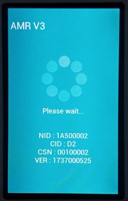
After getting the new Firmware, Relay is turned on and off.
This can also be done by using the Firmware Update option in the Device menu
Generally, the software identifies the relay with three modes and displays in the Preferences window:
Main Mode: When the software is connected to the relay and the relay is fully raised, Main Mode is displayed.
Bootloader Mode: When the software is connected to the relay and the relay is ready to get the new Firmware from the software, bootloader Mode is displayed.
Unknown: when the software is not connected to the relay or no Packet is received from the relay, Unknown is displayed.
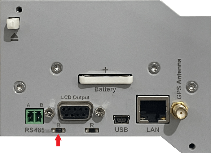
When the relay doesn't come up for any reason or Firmware has a problem, it is possible to manually place the relay in Bootloader Mode. To do this, the relay must first be turned off; when it is turned on, the Boot button must be pressed on the CPU card marked with the letter B and kept for 3 seconds after the power is connected. This put the relay in Bootloader Mode and makes it ready to get the new Firmware from the software; then click on the Firmware Update option in the Preferences window to send the new Firmware on the relay.
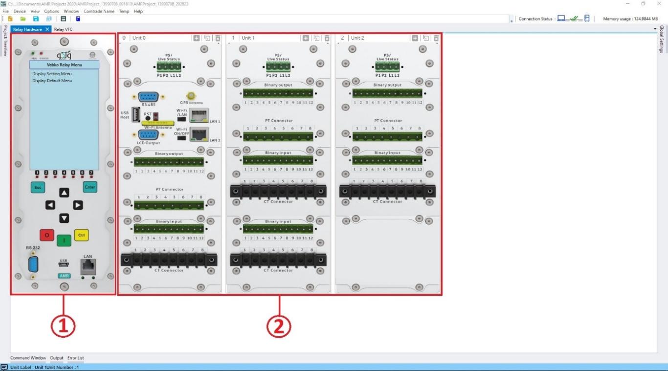
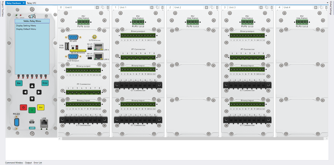
In general, based on what functions the relay is used to implement, it taken different hardware configuration determin at the time of ordering the relay. There is also the ability to upgrade hardware after ordering if you need to develop functions. To configure the relay, the relay hardware must first be implemented in the Relay Hardware section. In this section, a view of the front panel of the relay and the cards behind the relay are displayed.
Hardware relay configuration is possible in two ways:
Receiving settings from the relay
Creating hardware by working with units and cards
In general, the Vebko relay is able to recognize the type (Card Type) and serial number of the cards placed on the relay, but the cards placement should be introduced to the relay by the software, if needed, this hardware configuration, which includes the number of units, type and order of the cards, can be obtained from the relay. It should be noted that in order to do this, the software must be connected to the relay. To do this, you can receive these settings from the relay by clicking on the Read Hardware icon in the toolbar or selecting the Read Hardware from Relay option from the Device menu.
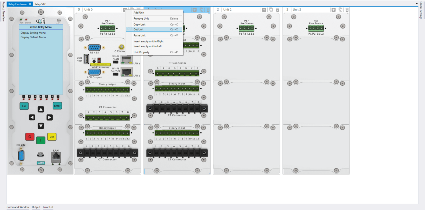
By right-clicking on the upper part of each unit and selecting the Add Unit option, a unit that only has a feeding card is added after the last unit. This can also be done by clicking on the Add Unit icon in the upper part of each unit.

By Right-clicking on each unit and selecting “Insert empty unit in left” one empty unit is added to its left by selecting the insert empty unit in right, an empty unit is added to its right.
To remove a unit right-click and select the Remove Unit or click on Remove Unit icon on the upper part of the unit, it to remove an icon.

The unit can also be removed by selecting the desired unit and pressing the delete key on the keyboard.
Note: Unit 0 cannot be deleted.
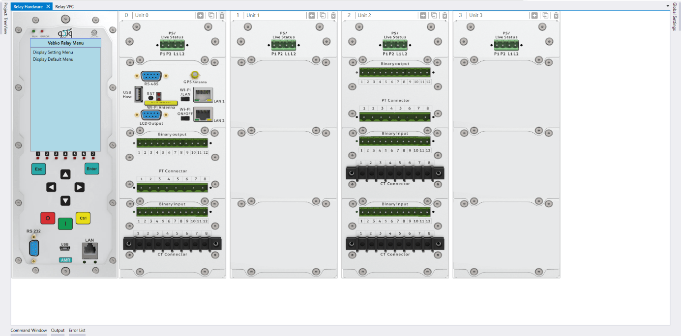
To copy a unit, the desired unit must first be saved in memory by right-clicking on it and selecting the Copy Unit option, then by right-clicking on each units and selecting the Paste Unit option, a copy of the unit can be created on the right side of the selected unit.

It is also possible to use ctrl+X and ctrl+V combination keys instead of selecting Copy Unit and Paste Unit options, respectively.
note: A copy of the unit can be added to the right by clicking on the Duplicate icon.
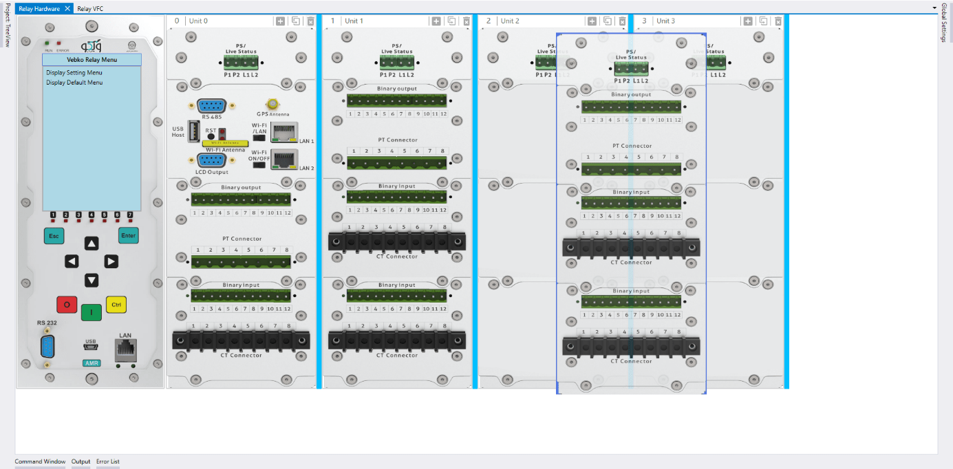
To make copy operation easier, you can create a copy of the unit in that section by pressing the ctrl key and dragging and dropping the desired unit at the blue intervals between the units.
To cut a unit, the desired unit must first be saved in memory by right-clicking on it and selecting the Cut Unit option, then right-clicking on each units and selecting the Paste Unit option the selected unit can be pasted to its right.
It is also possible to use combination keys ctrl+X and ctrl+V instead of selecting Cut Unit and Paste Unit options.
To make the job easier, you can paste the desired unit by pressing the shift key, drag and drop the desired unit at the blue intervals between the units, glue the desired unit in that part.
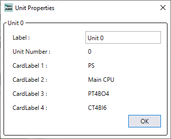
By double-clicking or right-clicking on each unit and selecting the Unit Property option, the Unit Properties window opens and the unit information including labels, unit numbers and labels of its cards are displayed. In this window, you can change the unit label in the Label field. Changes are saved by clicking on the OK option.
The label can be changed by clicking on the name of each unit in its upper part.
To add a new card or to change the type of card right-click on the card and place the pointer on the Change Card Type option, to see the list of cards displayed, by clicking on any of them, the selected card is added in that part.

note: Each relay can have only one CPU card. Also, each unit can have only one feeding card.
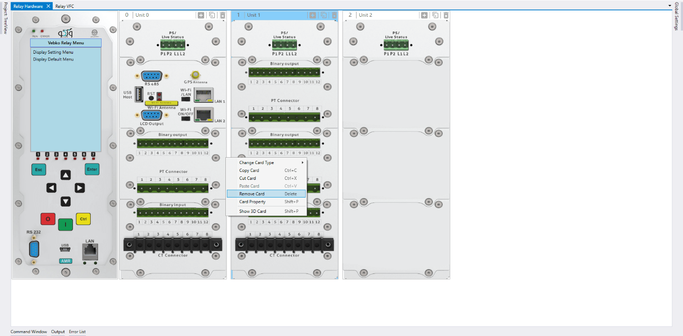
To delete a card, by right-clicking on the desired card and selecting the Remove Card option it can be deleted.
The card can also be deleted by selecting the desired card and pressing the delete key on the keyboard.
To copy a card, the card must first be saved in memory, right-click on the each and select the Copy Card option, then by right-clicking on each cards and selecting the Paste Card option, a copy of the card can be created there.

instead of selecting copy card and Paste Card options, use the combination keys like ctrl+C and ctrl+V, respectively.
To make the job easier, you can simultaneously press the ctrl key, drag and drop the desired card in the section related to other cards. This way a copy of the selected card is created.

To cut a card, it must first be saved in memory, right-click and select the Cut Card option, then by right-clicking on each card and selecting the Paste Card option, the card can be pasted in that section.

It is also possible to use ctrl+X and ctrl+V combination keys instead of selecting Cut and Paste Card options, respectively.
To make the cut operation easier, you can paste the card in that section by pressing the shift key, drag and drop the card in the other card section.
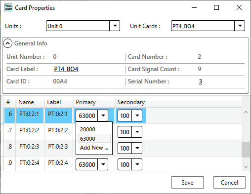
By double-clicking on each unit or right-clicking on it and selecting the Card Property option, the Card Properties window is opened. so the card information including unit number, card number, label, number of signals, ID and serial card are displayed. Also, the signal information of this card is available in this window. In this window, you can change the label in the card label field. By clicking on save option the changes are saved.

Note: In this window, you can also access other cards in other units. To do this, first, in the Units field, the desired unit is selected and then the card is selected in the Unit Cards field. If changes are made, the user is asked if the current card settings are to be saved, if you want to save the settings, you should click save.
If the desired value is not available, a new value can be added to Primary or Secondary by selecting the Add New option. For example, here the value of 230,000 volts for the primary and the value of 110 volts for the secondary are selected. By clicking on the Save option, the changes in this window are saved.
Similar to the previous case, the Card Properties window opens by double-clicking on the current card, in this window in the row of current signals starting with the letters CT, the conversion ratio of the network current transformers is specified. In the Primary column, the nominal current of the primary side and in the Secondary column, the nominal current of the secondary side of the current transformers is selected.
If the desired value is not available, a new value can be added to Primary or Secondary by selecting the Add New option. For example, here the value of 1000 amps for the primary and the value of 1 amp for the secondary is selected. By clicking on the Save option, the changes in this window are saved.

Note: In this window, you can also access the other cards in the other units. To do this, first, in the Units field, the desired unit is selected and then in the Unit Cards field the desired card is selected. If changes are made, first the user is asked if the current card settings are saved or no, if you want to save the settings, you should click on save option.
AMR modular relay of Vebko company supports various protection functions. Explanations of the capabilities and software environment of this relay have already been presented in the video related to differential protection test.
After connecting to the AMR relay at first, simply load the device's hardware configuration from the Device menu by selecting the Read Hardware from Relay option. The default password is 123456 to receive elements. At this point, a message is given to remove the signal, which if confirmed, if the current hardware is not the same as the relay hardware, the current hardware signals used in the VFC section are deleted.
It should be noted that the settings for the conversion ratio of voltage and current transformers are determined in the related card. Here, the current card conversion ratio is 200A to 1A and the voltage card conversion ratio is 63000 to 100V.
(First, enter the VFC page): As mentioned earlier in AMR software, the config of some of the most widely used functions, as an example, are placed in the software as samples; and the user can select any of them apply the desired changes and send the new settings to the relay. For this purpose, a set of functions can be seen in the Relay VFC tab and in the Temp Functions section. It should be noted that by selecting each Temp Function, the available blocks in the VFC are removed.
Here the Under Voltage function displayed with the name UV 27 is selected. In the configure of this function, to calculate the line-by-line voltages, first the relay voltage card signals are assigned to the Voltage Quantities block inputs and then assigned to the Undervoltage block. Also, current card signals connected to the current transformers (CT) of the same feeder are assigned to the Undervoltage block for current monitoring. Finally, undervoltage block output signals are assigned to Binary Outputs and relay LEDs by Output and LED blocks. The purpose is to test the Undervoltage function with AND logic, so the sample of line-by-line voltages are used.
By double-clicking on the Undervoltage block, two stages are defined here. The first stage with a 50V setting and a performance time of 1.5 seconds and a second stage with a 45V setting and a performance time of 1 second. The Drop Ratio value is also 1.2 for both stages by default. Since there is no need for Current Supervision, option I superv. is disabled.
After this, the pickup signals of both stages are removed from the unit with current monitoring and the necessary signals are added to the normal units without current monitoring. In the final step, these changes are applied to the relay to be prepared for testing.
In the next step, by running AMPro software and opening the AMT Under/Over Voltage Test, simply go to the Test Object Parameters section and enter the basic information. Testing this function can also be performed in AMT sequencer room, but in order to make the states and test management more comfortable, this process is performed in the AMT Under/Over Voltage Test.
First, the information is entered in the General Information section. This information can include relay type, serial number and other information such as post name and feeder/b number.
In the Test Setting section, the UV (27) option is selected. Here Vnom sec, 100 volts is selected. Also, the performance mode is located on AND logic to reduce the voltage of all three phases of the specified value to provide the test.
In order to evaluate the performaning of Under Voltage protection, two time tests (Trip time) and Voltage Performance Test (pickup/drop-off) are performed.
Assuming there are two performance stages for Under Voltage protection, regulatory voltage value, voltage type, performance time and more are entered in the Data Table section for both stages of operation. After this, in order to be more accurate in testing, continuous ramp option is selected in state setting section, C1 and C2 contacts are considered for detection of trip and pickup/drop-off, respectively. In addition to contact, the relay pickup status can be recorded with LED or even adjusted to instantaneous Under Voltage protection.
By entering the necessary settings in the Test Plan section, schedule the test in a way that both time test and voltage performance testing are performed. In the Fault Type section, by selecting the L1L2L3 option, states are created for the function test based on the Under Voltage of all three phases. By enabling Time Test, the state related to the performance time check is created. Vtest is the voltage value that the performance of the function in each stage is guaranteed. By selecting yes for PU Test and DOU Test elements, it is confirmed to perform pickup drop-off tests. In the PU Val. Assessment section, the evaluation of the pickup value of the function, in the PU Start section, the initial voltage of the pickup process, in the PU end section, the final voltage limit for the pickup test, and in the DOU End section, the final value for the drop-off test is entered. In the Total section, the total duration of the test is entered.
By Clicking on the Init Test option, creating states will be done based on user-imported settings. These states can be seen in the Table View window. This way, the test can be performed to evaluate the necessary items.
In the Measurement View section, in Assessment ramp tab you can see the assessment of the pickup drop-off and in the Time Assessment tab, you can see the performance time assessments of each stage can be seen.
Keep in mind that when the test reaches the second stage assessment section, a message appears to the user to disable the first stage in order to provide non-interference conditions. This can be done by removing elements related to the first stage from the blocks associated with pickup and trip. Another solution is to equalize the setting of two stages. For this purpose, once again refer to AMR software and set the first stage settings equal to the second stage settings the settings are then to be sent to the relay. In the end, the results are added to the report by clicking on the Add to Report option. These results are visible in the Report window.
AMR modular relay of Vebko company supports various protection functions. Explanations of the capabilities and software environment of this relay have already been presented in the video related to differential protection test.
After connecting to the AMR relay at first, simply load the device's hardware configuration from the Device menu by selecting the Read Hardware from Relay option. The default password is 123456 to receive elements. At this point, a message is given to remove the signal, which if confirmed, if the current hardware is not the same as the relay hardware, the current hardware signals used in the VFC section are deleted.
It should be noted that the settings for the conversion ratio of voltage and current transformers are determined in the related card. Here, the ratio of the current card conversion is 200A to 1A and the voltage card conversion ratio is 63,000 to 100V.
(First, enter the VFC page): As mentioned earlier in the AMR software, configuring some of the most widely used functions are placed in the software as samples. The user can send new settings to the relay by selecting each of them and applying the desired changes. For this purpose, a set of functions can be seen in the Relay VFC tab and in the Temp Functions section. It should be noted that by selecting each Temp Function, the blocks in the VFC are removed.
Here the overvoltage function displayed with the name OV 59 is selected. In the config of this function, to calculate the line-by-line voltages, First the relay voltage card signals are assigned to the Voltage Quantities block inputs and then assigned to the Overvoltage block. Finally, overvoltage output signals are assigned to Binary Output and relay LEDs by Output and LED blocks. Since the purpose is to test the overvoltage function with OR logic, analog signals related to the voltage sample must be applied directly to the overvoltage block to increase the voltage of each phase, the relay function should occur.
By double-clicking the Overvoltage block, two stages will be defined here. The first stage with a 65V set, performance time of 2 seconds and a second stage with a 70V set and a performance time of 4 seconds. In addition, Operation Quantity is placed on Vphn/V1/V2 to include single-phase performance. Finally, the changes are sent to the relay.
In the next step, by running AMPro software and opening the AMT Under/Over Voltage Test, simply go to the Object Parameters test section and enter the basic information. Testing this function can also be performed in AMT sequencer room, but in order to make the states and test management more comfortable, this process is performed in the AMT Under/Over Voltage Test.
Firstly, the information is entered in the General Information section. This information can include relay type, serial number and other information such as post name and feeder/b number.
In the Test Setting section, the OV (59) option is selected. Here Vnom sec, 100 volts is selected. Also, the performance mode is located on the OR logic to increase the voltage of each phase from the specified value to provide the test.
In order to evaluate the performance of overvoltage protection, two time tests (Trip time) and Voltage Performance Test (pickup/drop-off) are performed.
Assuming two performance stages for overvoltage protection, regulatory voltage value, voltage type, performance time and more are entered in the Data Table section for both stages of operation. After this, to be more accurate in testing, continuous ramp option is selected in state setting section; then C1 and C2 contacts are considered for trip diagnosis and pickup/drop-off, respectively. The status of the relay pickup can be recorded with LED in addition to contact, or even adjusting to instantaneous over-voltage protection.
By entering the necessary settings in the Test Plan section, schedule the test in a way that both time test and voltage performance testing are performed. In fault type, by selecting L1E, L2E and L3E, states are created to test the function based on the voltage increase of each phase independently. By enabling Time Test, the state related to the performance time check is created. Vtest is the voltage value at which the performance of the function in each stage is guaranteed. By selecting yes for PU Test and DOU Test elements, it will be confirmed to perform pickup drop-off tests. In the PU Val. Assessment section, the evaluation of the pickup value of the function, in the PU Start section, the initial voltage of the pickup process, in the PU end section, the final voltage limit for the pickup test, and in the DOU End section, the final value for the drop-off test is entered. In the Total section, the total duration of the test is entered.
By Clicking on the Init Test option, states are created based on user-imported settings. These states can be seen in the Table View window. This way, the test can be performed to evaluate the necessary items.
In the Measurement View section, in Assessment ramp, the assessment of the pickup drop-off can be seen. In the Time Assessment tab, the performance time assessments of each stage can be observed.
Keep in mind that when the test reaches the second stage assessment section, a message has appeared to tell the user to disable the first stage in order to provide the conditions for non-interference. This can be done by removing elements related to the first stage from the blocks associated with pickup and trip. Another solution is to equalize the setting of two stages. For this purpose, once again refer to AMR software, set the first stage equal to the second stage settings and the settings are sent to the relay.
In the end, the results are added to the report by clicking on the Add to Report option. The results are visible in the Report window.
AMR modular relay of Vebko company supports various protection functions. Explanations of the capabilities and software environment of this relay have already been presented in the video related to differential protection test.
After connecting to the AMR relay at first, simply load the device's hardware configuration from the Device menu by selecting the Read Hardware from Relay option. The default password is 123456 to receive elements. At this point, a message is given to remove the signal, which if confirmed, if the current hardware is not the same as the relay hardware, the current hardware signals used in the VFC section are deleted.
It should be noted that the settings for the conversion ratio of voltage and current transformers are determined in the related card. Here, current card conversion ratio is 200A to 1A and voltage card conversion ratio is 63,000 to 100V.
(First, enter the VFC page): As mentioned earlier in the AMR software, configuring some of the most widely used functions are placed in the software as samples the user can send new settings to the relay by selecting each of them and applying the desired changes. For this purpose, a set of functions can be seen in the Relay VFC tab and in the Temp Functions section. It should be noted that by selecting each Temp Function, the blocks in the VFC are removed.
Here the negative sequence overcurrent function displayed with the name NS 46 is selected. In this template, first, the signals of a current card are given to the Current Quantities block to create different current sequences in its output. In the default config of the Negative Sequence function, a block with different stages and signals of a current card with negative sequence is assigned to its input. Finally, output signals are assigned to Binary Outputs and relay LEDs by Output and LED blocks. To change the settings, simply right-click on each block to access a set of options.
By double-clicking on the Negative Sequence block, the settings for its various stages are visible. Here, the first stage with normal Inverse setting characteristic has a current of 0.1 amps, the TMS equals 1, and the two constant time stages with a current setting of 0.2 and 0.5A have a time setting of 1.5 and 0.5 seconds, respectively.
By making these changes, simply select Send Config and Setting to Relay from the Device menu again. This way, the settings and applied configuration are moved to the relay. (Cut from this part until the overcurrent room opens).
In the next step, by running AMPro software and opening the AMT Overcurrent room, it is enough to go to the Test Object Parameters section and create the test characteristic after entering the information. The test characteristic is created in the Elements tab in the Negative Sequence section. Therefore, the default characteristic in this section is removed first. First, a reverse time characteristic is created with a current setting of 0.1 amps and TMS=1. The next characteristic is created by current setting of 0.2 and a time of 1.5 seconds. Finally, the third characteristic is created by adjusting the current setting of 0.5 and the time of 0.5 seconds. Keep in mind that it is also possible to test this function using the Xrio file.
In order to evaluate the performance of negative sequence overcurrent function, two Trip Time and Pickup-Drop Off tests are performed. The purpose of Trip Time is to detect and evaluate the accuracy of the performance time of this function and the purpose of pickup-drop off test is to detect and evaluate the accuracy of the actual current of the performance threshold and the reset threshold of this function.
To perform this test three states ones including PreFault, Fault and PostFault are required. PreFault time is suitable for 500 milliseconds, fault time should be greater than the maximum trip time, and Post Fault time is at least 500 milliseconds. PostFault time should be increased if the drop-off is not instantaneous.
The suggested points for reduced time functions are 1.5 times, 2 times and 4 times the regulatory current, and for constant time curves, 1.5 and 2 times the regulatory current. These points are added to the fault type 12 to prepare the test. Keep in mind that due to the existence of three different characteristic, in some cases, the added points with the mentioned coefficients fall on the other characteristic. In these cases, other points are manually added on each characteristicto ensure accurate time performance.
To detect the regulatory current of the second and third units, two points can be added to 90 and 110 percent of the regulatory current of these units in order to perform a kind of pickup drop-off test for these characteristics. Once again, the Max Fault Time value is set based on the highest number inserted in the t nom section. By adding points, perform the test to check the performance of this function from the point of view of time accuracy.
In order to perform this test, it is first to determine how the diagnosis of pickup and drop-off is performed. This process can be done through a separate contact, like Start, Relay LED viewing, or changing the setting for the instantaneous of the function and using the trip contact. Here we used the relay pickup contact. You can also put the current fault value in the desired range. Here the fault value is considered 5% by default. The performance range of overcurrent curves in the AMR relay starts from 1.1 regulatory current in the relay. Therefore, first, by enabling the Active Range Limits option in the Overcurrent Protection Parameters window, Imin value are determined to be 1.1*0.1=0.11 Iref. In the next step, the current adjustment value for the pickup is placed on 0.1*1.1=0.11 amps. By adding this point, it is enough to perform the test and add the necessary elements to the report when it is finished.
After connecting to the AMR relay at first, simply load the device's hardware configuration from the Device menu by selecting the Read Hardware from Relay option. The default password is 123456 in order to receive elements. At this point, a message is given to remove the signal, which if confirmed, if the current hardware is not the same as the relay hardware, the current hardware signals used in the VFC section are deleted.
It should be noted that the settings for the conversion ratio of voltage and current transformers are determined in the related card. Here the ratio of current card conversion is 200A to 1A.
(First, enter the VFC page): As mentioned earlier in the AMR software, configuring some of the most widely used functions as examples are placed in the software and the user can send new settings to the relay by selecting each of them and applying the desired changes. For this purpose, a set of functions can be seen in the Relay VFC tab and in the Temp Functions section. It should be noted that by selecting each Temp Function, the blocks in the VFC are removed.
Here the directional overcurrent function displayed with the name OC 67 is selected. In Configuring, this function uses an OC Inverse block and two OC Definite blocks that have different settings and the signals of a current card are assigned to their input (from a measuring point). Finally, output signals are assigned to Binary Outputs and relay LEDs by Output and LED blocks. To change the settings, simply right-click on each block to access a set of options. Finally, the changes are sent to the relay.
In this video, by double-clicking on blocks that contain constant time stages for the directional overcurrent function, disables them and define the 1A and TMS current settings equal to 0.1 by double-clicking on the first stage, which is defined as reverse time. By double-clicking on the Direction block, the elements related to the directional function include rotation angle and ground polarization. After this, the changes will be sent to the relay by selecting send config and setting to relay option.
In the next step, by running AMPro software and opening the AMT Overcurrent room, it is enough to go to the Object Parameters test section and create the test characteristic after entering the information. Keep in mind that it is also possible to test this function using the Xrio file. Here, the current setting value is equal to 1 amp, TMS is 0.1. In the overcurrent test, it is required to set two parameters maximum torque angle and sector operation. To do this from the Overcurrent window and the Relay Parameters tab, the directional option is selected and from the Element tab, the Directional section is placed on forward. Then enter under the Define Element Directional Behavior tab and the maximum torque angle and Sector operation parameters are equal to -45 and 172 degrees, respectively.
In directional overcurrent relays, In order to better performance of relay, in orientation and reaching the MTA value ,the rotation of the reference voltage angle is used.. The performance area or forward area in this relay is set from -131 degrees to +41 degrees.
In order to investigate the directional overcurrent function, in addition to the time of operation and current, the angle of performance should also be investigated. For this purpose, performance time tests are performed along with amplitude and phase tests.
In the time test, the accuracy of the performance time is investigated and in the amplitude and phase test, the detection and evaluation of the accuracy of the actual current and the actual angle of the performance threshold and reset threshold are considered.
Cross Polarized method is used in AMR Vebko relay, i.e. using healthy phases to detect fault direction. For example, in case of faults in phase A, the relay uses VBC reference voltage and IA current to detect the fault current direction. The Forward or Reverse area means the part where the relay must detect the fault will be determined by the start angle and end angle.
In order to test the DOC function, three states are considered. The first state for 500 milliseconds, normal conditions this means that it will inject a nominal voltage with zero current.
In the second state, the fault conditions are applied and the current is selected for all phases of L1E-L2E-L3E in the range of 2 to 4 times the nominal current. The duration of this state should be greater than the nominal time of the relay trip.
The third state will also be activated as post-Fault with zero voltage and current for 500 milliseconds. In order to see better performance of the function, from the View menu, the Detail View window opens.
After adding double points and four times the regulatory current at the best possible angle in terms of performance of the function i.e. -45 degrees for the L1E-L2E-L3E falt types, a point in the No Trip area (here at an angle of 135 degrees) is tested.
Due to the nature of the two-phase fault, the currents in this fault will have a phase difference of 180 degrees so that the 3I0 current is not created and the 67N function is not activated.
In order to perform the Pickup-Drop off test, you can also use a relay or LED contact and even a setting change to instantaneous the function.
For this purpose, three states are needed for example in the first state, the normal network conditions, applied, in the second state the pickup test and in the third state the drop-off test is performed. In the second state, for pickup and drop-off test of angle, the current value will be twice the regulatory current. these states are performed in the Overcurrent room automatically by entering the settings by the user.
The performance range of overcurrent curves in the AMR relay starts from 1.1 regulatory current in the relay. Therefore, first, by enabling the Active Range Limits option in the Overcurrent Protection Parameters window, the Imin value is set to 1.1 Iref. In the next step, the current adjustment value for the pickup test of the current value is placed on 1.1*1=1.1 amps. This test is performed at the best possible angle in terms of relay performance i.e. -45 degrees.
After the current pick up-drop off, it is time to Pick up-drop off on the angle. For this purpose, as mentioned above, the current value is applied twice as much as the regulatory current, and once the trend is performed for the upper limit of the angle, i.e. 41 degrees, and once for the lower limit of the angle, i.e. -131 degrees. By adding the necessary tests and performing, you can finally add favorites items to the report.
AMR modular relay of Vebko company supports various protection functions. Explanations of the capabilities and software environment of this relay have already been presented in the video related to differential protection test.
After connecting to the AMR relay at first, simply load the device's hardware configuration from the Device menu by selecting the Read Hardware from Relay option. The default password is 123456 to receive elements. At this point, a message is given to remove the signal, which if confirmed, if the current hardware is not the same as the relay hardware, the current hardware signals used in the VFC section are deleted.
It should be noted that the settings for the conversion ratio of voltage and current transformers are determined in the related card. Here the ratio of current card conversion is 200A to 1A.
(First, enter the VFC page): As mentioned earlier in the AMR software, config of some of the most widely used functions as are placed in the software as sample the user can send new settings to the relay by selecting each of them and applying the desired changes. For this purpose, a set of functions can be seen in the Relay VFC tab and in the Temp Functions section. It should be noted that by selecting each Temp Function, the blocks in the VFC are removed.
Here the non-directional overcurrent function displayed under the name OC 50/51 is selected. In configuring this function, an OC Inverse block and two OC Definite blocks are used. They have different settings and the signals of a current card are assigned to their input (from a measuring point). Finally, output signals are assigned to Binary Outputs and relay LEDs by Output and LED blocks. To change the settings, simply right-click on each block to access a set of options. Finally, the changes are sent to the relay.
In this video, by double-clicking on blocks that contain constant time stages for non-directional overcurrent function, disables them and define the 1A and TMS current settings equal to 0.1 by double-clicking on the first stage, which is defined as reverse time.
By making these changes, simply select Send Config and Setting to Relay from the Device menu again. In this way, the settings and configuration applied are moved to the relay.
In the next step, by running AMPro software and opening the AMT Overcurrent room, it is enough to go to the Object Parameters test section and create the test characteristic after entering the information. Here, a reverse time characteristic is created by 1A and TMS=0.1 current settings. Keep in mind that it is also possible to test this characteristic using the Xrio file.
In order to evaluate the performance of non-directional overcurrent function, two Trip Time and Pickup-Drop Off tests are performed. The purpose of Trip Time is to detect and evaluate the accuracy of the performance time of this function and the purpose of pickup-drop off test is to detect and evaluate the accuracy of the actual current of the performance threshold and of reset threshold of this function.
Three states including PreFault, Fault and PostFault are required to perform this test. PreFault time is suitable for 500 milliseconds, fault time should be greater than the maximum trip time, and Post Fault time is at least 500 milliseconds. PostFault time should be increased if the drop-off is not an instantaneous.
The suggested points for reduced time functions are 1.5 times, 2 times and 4 times the regulatory current, and for constant time curves, 1.5 and 2 times the regulatory current.
To detect the regulatory current of the second unit, two points can be added to the amount of 90 and 110 percent of the regulatory current of the second unit.
By adding points, perform the test to check the performance of this function from the point of view of time accuracy.
In order to perform this test, first determine how the diagnosis of pickup and drop-off is performed. This process can be done through a separate contact, namely Start, Relay LED viewing, or changing the setting for instantaneous function and using the trip contact. Here we used the Contact Pickup Relay. You can also put the current fault value in the desired range. Here the fault value is considered 5% by default. The performance range of overcurrent curves in the AMR relay starts from 1.1 regulatory current in the relay. Therefore, first, by enabling the Active Range Limits option in the Overcurrent Protection Parameters window, the Imin value is set to 1.1 Iref. In the next step, the current setting value for the pickup is placed on 1.1*1=1.1 amps. (as it is shown)
By adding points, it is enough to perform the test and add the necessary elements to the report when it is finished.
AMR modular relay of Vebko supports various protection functions. Explanations of the capabilities and software environment of this relay have already been presented in the film related to differential protection test.
After connecting to the AMR relay at first, simply load the device's hardware configuration from the Device menu by selecting the Read Hardware from Relay option. The default password is 123456 in order to receive elements. At this point, a message is given to remove the signal, which, if confirmed, the current hardware signals used in the VFC section will be deleted, if the current hardware is not the same as the relay hardware.
It should be noted that the settings for the conversion ratio of voltage and current transformers are determined in the related card. Here, the ratio of the current card conversion is 200A to 1A and the voltage card conversion ratio is 63,000 to 100V.
(First, enter the VFC page): As mentioned earlier in the AMR software, configuring some of the most widely used functions as examples are placed in the software and the user can send new settings to the relay by selecting each of them and applying the desired changes. For this purpose, a set of functions can be seen in the Relay VFC tab and in the Temp Functions section. It should be noted that by selecting each Temp Function, the blocks in the VFC are removed. Here the Distance function displayed with the name Dist is selected.
As can be seen in this Temp Function, the signals of analog relay cards are assigned to the inputs of the Distance block, as well as to calculate line-by-line voltages, voltage card signals are given to the Voltage Systems block and then assigned to the Distance Block. Finally, distance output signals are assigned to Binary Outputs and relay LEDs by Output and LED blocks. You can also access the settings of this function by double-clicking on the Distance block.
By scrolling on the signals of each block, more signals are displayed if available. Also visible from the Signals tab, the set of output signals assigned to the distance block.
After applying the desired changes, using the Ctrl+ E combination keys or by using the File menu and selecting the Export XRio option, the XRio file is downloaded from the software as an output containing the distance function settings.
Next, by running AMPro software and opening the AMT Distance room, simply upload the Xrio file you saved in the software environment in the previous step. By loading the relay distance characteristic, conduct the test based on the periodic testing system of Iran's power transmission network protection systems.
Firstly, shot test is performed, which aims to evaluate the time of different tripe zones. The Pre Fault value is at least 1 second and the Post Fault value is at least 500 milliseconds. In order to perform this test, we place points on 80% of the value of each zone in line with the real axis and also in line with the angle of the line.
In line with the real axis, the test will be performed for all phase-to-ground characteristics in the A-N and phase-to-phase fault loops in the B-C and ABC fault loops. In line angle, testing is performed for all phase-to-ground characteristics in the C-N and phase-to-phase fault loops in A-B and ABC fault loops. By performing the test, the performance time for the added points can be seen in different zones.
In the second step, the Test Check is performed to check the performance time and range of the zones in the upper and lower part of the Rich value by drawing the lines on the R, X axes and in line with the angle of the line. Here, in order to avoid prolonging the test process, the check test is performed only for three-phase fault type.
By performing of this test, the results of the studies will once again be visible. In the final step, search test is performed with the aim of searching the curve, detecting and evaluating the real range of each distance relay zones. For this purpose, search line should be selected in line with the R, X, angle of the line and the location of the collision of the sides.
This test is performed in line with the real axis and in a way that passes through all zones as a one-time repetition for each search line, for all phase-to-ground characteristics in the A-N and phase-by-phase fault loops in the B-C and ABC fault loops. Here, in order to avoid prolonging the test process, this test is only performed for the ABC fault loop.
In line angle and so that we cross all zones again, once repetition is performed for each line and for all phase-to-ground characteristics in the C-N and phase-by-phase fault loops in the A-B and ABC fault loops. Finally, at the collision site, a repeat is performed once for each search line for phase-to-ground characteristic in the A-N fault loop and phase to phase in the B-C fault loop.
As mentioned above, in order to prevent the prolongation of the test process, these tests are only performed for the ABC fault loop. When the test is finished, you can specify the elements in the report and save the output in different formats such as PDF.
AMR multi-function relay with modular and expandable hardware structure enables the development of various functions. The AMR relay has four regulatory groups and can save Event log, Trip Log and Comtrade. The relay has also successfully passed tests of protection relays in accordance with the IEC-60255 standard.
In order to configure this relay, you can use AMR software. The Relay Hardware software module enables relay hardware configuration and Relay VFC module, allowing logic writing and implementation of various functions from easiest to most complex configurations. Also, using the Signal Routing module, functions can be implemented in the fastest way. After adjusting the settings, it is possible to help the relay test more easier through test devices by receiving the Xrio file as an output containing the functions settings. The AMR software can be downloaded from the website of The Vebko Company (Vebko.org). First, the software connects to the relay using the LAN cable and entering the relay IP in the Communication window.
It should be noted that the settings for the conversion ratio of voltage and current transformers are determined in the related card. Here, the ratio of the current card conversion is 200A to 1A and the voltage card conversion ratio is 63,000 to 100V.
(First, enter the VFC page): As mentioned earlier in the AMR software, configuring some of the most widely used functions as examples are placed in the software and the user can send new settings to the relay by selecting each of them and applying the desired changes. For this purpose, a set of functions can be seen in the Relay VFC tab and in the Temp Functions section. It should be noted that by selecting each Temp Function, the blocks in the VFC are removed.
Here the differential function displayed with the name Diff is selected. In Config of this function, the signals of the current cards are connected to the differential block input. Finally, differential block output signals are assigned to Binary Outputs and relay LEDs by Output and LED blocks. You can access the settings of this function by double-clicking on the differential block.
After applying the desired changes, using the Ctrl+ E combination keys or by using the File menu and selecting the Export Xrio option, the Xrio file is downloaded from the software as an output containing differential function settings. Next, by running AMPro software and opening the AMT Differential room, simply upload the Xrio file you saved in the software environment in the previous step.
By loading the differential characteristic of the relay, conduct the test based on the periodic testing system of Iran's power transmission network protection systems. Here we select PreFault and Postfault time 500 milliseconds and Fault time 200 milliseconds.
Firstly, points should be selected within blocking and Tripping areas. The relay performance time during testing must match the time set in the differential relay. At each slope of the curve, test points should be established at least in the characteristic breakpoints and outside of the current tolerance and close to it and on either side of the yield curve. In the lower parts of the characteristic, inactivity and in the upper parts of the characteristic, the moment performance must be recorded. In order to avoid prolonging the test time, fault types L1-E, L2-L3 and L1L2L3 are selected.
In the second step, the Check Test will be performed to calculate the performance and Inactivity on both sides of the characteristic, based on the time of the shots performed. This test is performed in fault types L1-E, L2-L3 and L1L2L3.
In the next step, by using Search Test, we evaluate the real curve of differential protection performance. According to the system, in search test, at least two search lines should be selected on the performance curve for each part of the curve slope, one of these lines is better to be in the characteristic fracture area. This test is performed in fault types L1-E, L2-L3 and L1L2L3.
As one of the functional tests, you can use pickup drop feature for differential characteristic. The three options Primary Side, -Secondary Side and bias allow pickup drop for differential component on the primary, secondary side as well as bias current, respectively. For this purpose, just add points for different Fault Type and run the test. Here, the drop-off pickup is evaluated for all types on primary and secondary sides.
Another function test, is available from AMT Differential's Room Stability tab. In this section, considering Idiff=0, you can specify the bias value as a coefficient against the nominal current to check the trans stability in this case. This test is performed in all fault types. When the test is finished, you can specify the elements in the report and save the output in different formats such as PDF.